Plastic injection moulds: which types exist and when to use each
One cavity or several, cold or hot runner, two plates or three. We explain what each decision changes in the cost of the mould, the cycle time and the finish of your part.
Technical14 min read
In brief
- The two-plate mould is the most widely used type and is simpler than the three-plate mould, which lets you place the gate at the centre of the part in exchange for a more expensive mould and a longer opening stroke.
- A cold runner needs less investment and makes colour changes easier, while a hot runner saves material and usually shortens the cycle, although at low volumes it may not pay off.
- From four cavities upwards, the cavities may fill differently, even when the runners are symmetrical.
- Slides, angled lifters and unscrewing mechanisms deal with undercuts and threads, but they make the mould more complex.
- It is worth agreeing in writing on the mould class and the number of cycles it must withstand.
Before an injection-moulded part can be made, you have to decide what its mould will be like. That decision sets much of what the mould will cost, how long each cycle will take and how the part will look. Here we explain what types exist, how they work inside and when each one makes sense.
We write from our factory in Tibi (Alicante), where we mould with machines from 100 to 500 t of clamping force. If you would like to see first how an injection moulding machine works, the technology section of our home page takes you through the cycle of a part step by step.
What is an injection mould and what are its parts called?
Link to the section What is an injection mould and what are its parts called?An injection mould is an assembly of machined metal plates with one or more cavities, which the injection moulding machine fills with molten plastic at high pressure. The mould also acts as a heat exchanger, and inside it the plastic solidifies in the shape defined by the cavitySource 1. These are the parts we will refer to.
- Cavity and core. The cavity is the hollow that gives the part its shape, and the core forms its interiorSource 1.
- Parting line. This is the surface along which the two halves of the mould separate when it opensSource 1.
- Sprue, runners and gate. The plastic arrives from the machine nozzle through the sprue, is distributed through the runners and enters the cavity through the gate, a passage that is generally small and the first thing to solidifySource 1.
- Runner. This is the plastic that solidifies in the runner system and leaves the mould every cycleSource 2Source 3.
- Ejectors. These are pins that push the part out of the mould when it opensSource 1.
- Cooling and vents. Water or another fluid circulates through channels to control the temperature of the surfaces in contact with the plastic, and air escapes from the cavity through very fine ventsSource 1.
The gate leaves a mark
However small it is, the gate leaves a mark on the part, and the mark differs from one system to anotherSource 4. It is worth deciding early where it can go without affecting a visible surface.
Two-plate or three-plate mould?
Link to the section Two-plate or three-plate mould?The two-plate mould
Link to the section The two-plate mouldThis is the most widely used type of mould. It has a single parting line, so the runners and gates have to lie on it in order to come out when the mould opens. Compared with a three-plate mould, it is cheaper, simpler to make and has a shorter cycleSource 5.
The part and the runner come out together. With an edge gate, which fills the part through its edge from the parting lineSource 1, they have to be separated afterwards in a secondary operationSource 6. With a submarine gate, on the other hand, the gate is cut from the part during ejectionSource 6. And if, with several cavities, the runners cannot be balanced on that single parting line, you may need a three-plate mould or a two-plate mould with a hot runnerSource 5.
The three-plate mould
Link to the section The three-plate mouldA runner stripper plate is added between the clamping plate on the fixed side and the A plate, which holds the cavity, and the mould then has at least three parting linesSource 7Source 8. The plastic enters through a pin-point gate, an opening from a few tenths of a millimetre to one and a half millimetres across, which is torn off the part when the mould opensSource 6Source 1.
Its advantage is that the gate can go at the centre of the part or at several points, the runner separates on its own, and a hot runner, which is more expensive, can often be avoidedSource 7. In return, the mould costs more and needs more maintenance, the cycle is longer and the machine has to open considerably furtherSource 7Source 8.
Removing the parts and the runner by robot is also harderSource 7. This is worth bearing in mind when removal is automated, as it is in our case, where we use a Cartesian robot.
The runner does not disappear
A runner that separates on its own is still a runner. A three-plate mould still produces one every cycle, and it is usually heavierSource 7.
How a three-plate mould opens
Link to the section How a three-plate mould opensThis mould works thanks to the order in which its plates separate. A technical series on three-plate mould design recommends this sequenceSource 9Source 8.
- First, the line between the stripper plate and the A plate opens a few millimetres, generally no more than 3 to 6 mm. The gate breaks while the part is still held between cavity and core, and puller pins keep the runner on the stripper plateSource 9.
- The main parting line, the one that separates the cavity from the core, opensSource 8.
- Stop bolts or limit bars, or a sequencing latch, pull the A plate along and open the runner parting line fullySource 8.
- Once that line is fully open, the stripper plate separates from the clamping plate and the runner dropsSource 8Source 10.
- The ejectors push the parts out of the mouldSource 1.
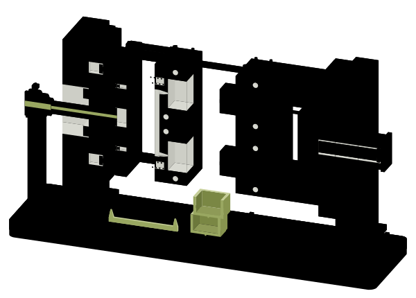
Cutaway model of a three-plate injection mould mounted in a machine on a bench, fully open. The stripper plate has moved a few millimetres away from the fixed clamping plate. The runner parting line has opened between the stripper plate and the cavity plate, and the runner has dropped through it and lies in its tray below the mould. The main parting line has opened between the cavity plate and the core plate, and the two parts have dropped through it into another tray. Limit bars on the plates set the order of the openings, and the scale on the bench shows the total stroke.
According to that series, if the main parting line opened first, the gate could distort the part, leave a taller vestige or even pull the part off the coreSource 9. Even so, opening the main parting line first is also common, for example with delay latches, and the pin-point gate is then torn off as the cavity separatesSource 6Source 11. When the runner is left to drop, it needs room to fall freelySource 8. If a robot removes it, a moulded peg can be added that holds it on the stripper plate until the robot picks it upSource 7.
Cold runner or hot runner?
Link to the section Cold runner or hot runner?This choice affects the investment, the material left over each cycle and how easily you can change colour.
Cold runner
Link to the section Cold runnerIn a cold runner mould the runner channels are not heated and the runner comes out with the parts every cycleSource 2Source 3. The investment is lower, there is less thermal variation because no heaters or controllers are needed, the previous colour does not stay in the runners and the gate can go wherever suits the part. On the other hand, the runner has to be removed and reground for reuse, and material costs are higherSource 2.
Hot runner
Link to the section Hot runnerA hot runner is an assembly of heated components that carries the molten plastic to the cavities. Its manifold distributes the plastic entering the mould among several nozzlesSource 3. The part comes out already separated and cycles are usually fasterSource 12.
Its costs are less visible. The plastic waiting in the manifold adds residence time, the time the material spends moltenSource 13. Colour changes take time, material and purging compound, maintenance has to be allowed for, leaks or stoppages can generate waste, and the gate locations are fixed by the manifoldSource 2.
A thermal gate leaves a protruding vestige of one third to one half of the gate diameter, and is reserved for parts where gate quality is not criticalSource 4Source 12. A valve gate closes the gate with a moving pin and leaves a small mark the size of the gate, with no drooling or stringingSource 12Source 4. It is more expensive, but it lets you open the gates in sequence and decide where the weld lines fall, the marks that form where two plastic flow fronts meetSource 4.
Low annual volumes
A full hot runner may not pay off when annual volume is low. It is worth considering a combination with a cold runner, or at least a heated sprueSource 13, and in many projects a cold runner is more viable than a hot runnerSource 2.
Insulated runner
Link to the section Insulated runnerThis is a hot runner without heating, with runners so thick that the plastic stays molten as long as the mould runs continuously. It only works with commodity plastics such as polypropylene (PP) and polyethylene (PE), and if the mould stops, the runner freezes and the mould has to be opened to remove itSource 14.
How many cavities does the mould need?
Link to the section How many cavities does the mould need?One cavity or several
Link to the section One cavity or severalWith a single cavity, there are no differences between cavities to keep an eye on. With several, each shot produces more parts, but the runners have to distribute the plastic evenlySource 5.
Symmetrical runners are not enough. The plastic heats up through friction as it flows, and not uniformly across the runner cross-section. From four cavities upwards this causes filling differences, and in moulds with eight or more cavities the worst cases can even be seen with the naked eye. The parts come out with different density, shrinkage and warpage, and a well-designed runner layout improves uniformitySource 15.
Family mould
Link to the section Family mouldA family mould produces different parts in the same mould, such as a box and its lid, and helps reduce the total investment in mouldsSource 16. The parts usually need to be similar in size, weight, wall thickness and volume, because they are all moulded with the same parametersSource 16. They also have to be made of the same material and produced in the same quantitySource 17. If they are very different, one solution is to control each cavity separately with valve gatesSource 16.
Stack mould
Link to the section Stack mouldA stack mould has two parting lines instead of oneSource 18. It can almost double the output of the machine with a similar clamping force, although up to 15% more is sometimes needed, and only the opening and closing time is added to the cycleSource 18Source 19. It suits flat parts better than parts with deep coresSource 18. In return, the mould has a greater shut height and needs a longer opening stroke, so you have to check that it fits the machineSource 18.
What if the part has undercuts or threads?
Link to the section What if the part has undercuts or threads?An undercut is a feature of the part that is trapped in the mould and prevents it from being ejected in a straight lineSource 1, such as a side hole or a thread. It is dealt with by changing the geometry or by adding mechanisms to the mouldSource 20.
- Slides. These are blocks that move in from the side when the mould closes and retract when it opensSource 20. They can be driven by an angle pin, which moves them sideways, away from the part, as the mould opensSource 21, and a retainer holds them back while the mould is openSource 22.
- Angled lifters. They release internal undercuts by converting the forward movement of the ejector plate into a sideways movementSource 20Source 23.
- Hand-loaded inserts. These are metal pieces that an operator places in the mould every cycleSource 20. They simplify the mould at the cost of manual work.
- Unscrewing. A threaded part may have to be unscrewed from the core before it can come out, and the gears that rotate the core can take up a lot of space in the mouldSource 24.
- Collapsible cores. Spring-loaded segments form the inside of a cap and, when the centre pin is withdrawn, collapse towards the centre to release itSource 25.
Before adding a mechanism
Every slide, angled lifter or unscrewing mechanism makes the mould more complexSource 20Source 24. It is worth checking with whoever is going to make the part whether a change in geometry would avoid the undercut.
Can several materials be combined in one part?
Link to the section Can several materials be combined in one part?Yes. Insert moulding encapsulates a metal component in plastic, such as a threaded insert that gives a stronger assembly. The bond is mechanical, so the insert is designed for the plastic to grip itSource 26.
Overmoulding adds a layer of plastic over a part that has already been moulded, for example a soft, elastic layer over a rigid body to give a non-slip grip. The bond can be chemical or mechanical, and it is best not to leave edges of the overmoulded material exposed, so that it does not peel offSource 26.
Two-component moulding injects two materials in the same cycle, with a single mould and a machine with two injection unitsSource 27. To make room for the second material, a rotary platen mounted on the machine moves the first shot to the second-shot cavity, or an index plate built into the mould transfers it to a different core, a task that a robot performs in some casesSource 27. Alternatively, the mould itself, usually without opening, can move part of the core or cavitySource 27. Moulding a part on one machine and overmoulding it in another mould on a different machine is a related process that falls outside this definitionSource 27.
How many cycles does a mould last and which class should you choose?
Link to the section How many cycles does a mould last and which class should you choose?Moulds can be made of aluminium, soft or pre-hardened steels, or hardened steels, and their life also depends on how they are built and on the cleaning, lubrication and maintenance they receiveSource 28. The SPI classes, from the former Society of the Plastics Industry, now the Plastics Industry Association, provide a common language for discussing that lifeSource 29.
| Class | Expected life | Typical use |
|---|---|---|
| 101 | More than one million cycles | Very high production, the most expensive mouldSource 30Source 28 |
| 102 | Half a million to one million | Medium or high productionSource 30Source 29Source 28 |
| 103 | Up to half a million | Medium production, the most common price rangeSource 30Source 28 |
| 104 | Up to one hundred thousand | Low productionSource 30Source 29Source 28 |
| 105 | 500 at most | Prototypes, built in the most economical waySource 30Source 29Source 28 |
The sources agree on the order of magnitude, but not always on the exact limits of each classSource 30Source 29Source 28. One of them also uses a 400 series for moulds used on machines of 400 tons or moreSource 30. As it is a US source, these are most likely short tons, about 360 t.
Put it in writing
Agree in writing on the mould class, the number of cycles it must withstand and who is responsible for its maintenance, which has a major bearing on its lifeSource 28. Our article on how to request an injection moulding quote explains what else is worth preparing.
Which mould system suits your part?
Link to the section Which mould system suits your part?The table summarises the above. These are general trends, and every part needs its own assessment.
| System | Gate | Runner | Cost and complexity | A good fit when |
|---|---|---|---|---|
| Two-plate, cold runner | On the parting line, at the edge or submarineSource 5Source 6 | Comes out with the part | Cheaper and simpler than a three-plate mouldSource 5 | The part can take a gate at its edge |
| Three-plate, cold runner | At the centre or at several pointsSource 7 | Heavier, separates on its ownSource 7 | More expensive, more maintenance and a longer opening strokeSource 7 | You need a centre gate without a hot runner |
| Hot runner, thermal gate | Flexible at the design stageSource 14, fixed once the manifold is madeSource 2 | Little or none | More investment and maintenance than a cold runnerSource 2 | High volume and a gate mark that is not criticalSource 13Source 12 |
| Hot runner, valve gate | Flexible at the design stageSource 14, fixed once the manifold is madeSource 2 | Little or none | More expensive than a thermal gateSource 4 | Cosmetic parts, family moulds and control of weld linesSource 4 |
| Insulated runner | Flexible at the design stage, as with other hot runnersSource 14 | Little, as long as the mould does not stop | No heating or temperature controlSource 14 | Polypropylene or polyethylene in continuous runsSource 14 |
How does a blow mould differ?
Link to the section How does a blow mould differ?We also manufacture by blow moulding, so this is worth clarifying. In blow moulding, a tube of molten plastic or a heated preform is inflated with compressed air inside the mould, producing hollow, lightweight parts such as bottlesSource 31. Because the pressures are lower than in injection moulding, the mould can be made from cheaper, less durable materials, usually aluminium, stainless steel or beryllium-copper alloysSource 31.
The plates and runners described in this article are specific to injection moulding. In the frequently asked questions on our home page, we summarise when each process is used.
Frequently asked questions about injection moulds
Link to the section Frequently asked questions about injection mouldsWhat mould do I need for my part volume?
Link to the section What mould do I need for my part volume?It depends on how many parts you need per year and for how many years. That figure guides the mould class, the number of cavities and whether a hot runner pays offSource 28Source 13. It is worth being clear about it before you request a quote.
Is a hot runner always cheaper?
Link to the section Is a hot runner always cheaper?Not necessarily. It avoids the runner, but it adds investment, maintenance and time at every colour change, and at low annual volumes it may not pay offSource 2Source 13.
Does the type of mould affect colour?
Link to the section Does the type of mould affect colour?It affects colour changes. With a cold runner, the runners are emptied every cycle, whereas with a hot runner a colour change takes time, material and purging compoundSource 2. If the colour of your part is critical, you may be interested in our article on colour measurement in plastics.
Shall we look at the mould for your part together?
Link to the section Shall we look at the mould for your part together?At Bersil we manufacture by plastic injection and blow moulding in Tibi (Alicante), with injection moulding machines from 100 to 500 t of clamping force and semi-automated processes. From your very first call, you deal with a member of our team.
Tell us what part you need and in what quantity, and we will study it with you. You can talk to our team or first see what backs up our quality.
Sources
Link to the section SourcesIf you would like to learn more about plastic injection and blow moulding, these sources will help you understand the field better. They are the ones we used to write this article.
- Glossary of TermsHelp documentation for injection moulding simulation software, 2018Back to the first citation of source 1
- Choosing Between Cold and Hot Runner SystemsMoldMaking Technology, 2017Back to the first citation of source 2
- Hot runnerWikipedia, 2026Back to the first citation of source 3
- Why Choose a Valve-Gated Hot Runner?MoldMaking Technology, 2001Back to the first citation of source 4
- Two-plate moldsHelp documentation for injection moulding simulation software, 2015Back to the first citation of source 5
- Automatically trimmed cold gatesHelp documentation for injection moulding simulation software, 2017Back to the first citation of source 6
- How to Design Three-Plate Molds, Part 1Plastics Technology, 2023Back to the first citation of source 7
- How to Design Three-Plate Molds, Part 3Plastics Technology, 2024Back to the first citation of source 8
- How to Design Three-Plate Molds, Part 2Plastics Technology, 2023Back to the first citation of source 9
- How to Design Three-Plate Molds, Part 4Plastics Technology, 2024Back to the first citation of source 10
- Tailored latch locks: Finding the right solution for your mouldETMM, European Tool & Mould Making, 2020Back to the first citation of source 11
- Revisiting Some Hot Runner FundamentalsMoldMaking Technology, 2020Back to the first citation of source 12
- How to Make an Informed Hot Runner DecisionMoldMaking Technology, 2020Back to the first citation of source 13
- Internally heated runner provides better heating control and better economyPlastemart, n.d.Back to the first citation of source 14
- The Real Cause of Multi-Cavity Mold ImbalancesMoldMaking Technology, 2012Back to the first citation of source 15
- How to Better Balance Family MoldsMoldMaking Technology, 2019Back to the first citation of source 16
- Family ToolingDesign guide from a custom parts manufacturer, n.d.Back to the first citation of source 17
- Hot Runner Stack Molds: A Great Cost-Cutting SolutionMoldMaking Technology, 2008Back to the first citation of source 18
- Multi-Parting Line and Multi-Material SystemsMoldMaking Technology, 2007Back to the first citation of source 19
- Conquering Undercut Design Issues with Side-actions, Inserts, and Shut-offsDesign guide from a custom parts manufacturer, n.d.Back to the first citation of source 20
- US5234329A, Angle pin assemblyUnited States Patent and Trademark Office, 1993Back to the first citation of source 21
- US6443723B1, Slide retainer for an injection moldUnited States Patent and Trademark Office, 2002Back to the first citation of source 22
- Angles Stop Negative Areas from Undercutting the Injection ProcessMoldMaking Technology, 2013Back to the first citation of source 23
- Unscrewing Core Design Provides Fast, Accurate Core PositioningMoldMaking Technology, 2006Back to the first citation of source 24
- Collapsible Core Technology Saves Time, Maintenance and MoneyMoldMaking Technology, 2012Back to the first citation of source 25
- Overmolding and Insert Molding Design GuideDesign guide from a custom parts manufacturer, n.d.Back to the first citation of source 26
- Multi-Component Molding: Which Way Should You Go?Plastics Technology, 2014Back to the first citation of source 27
- What to Know About Injection Molding Tooling LifeTechnical article from an on-demand manufacturing platform, 2023Back to the first citation of source 28
- Classification of Plastic Injection MoldsTechnical blog of an industrial manufacturer, 2019Back to the first citation of source 29
- SPI Class SummaryTechnical summary from a plastic injection moulding company, 2014Back to the first citation of source 30
- Blow Molding vs. Injection MoldingTechnical article from an on-demand manufacturing platform, 2024Back to the first citation of source 31